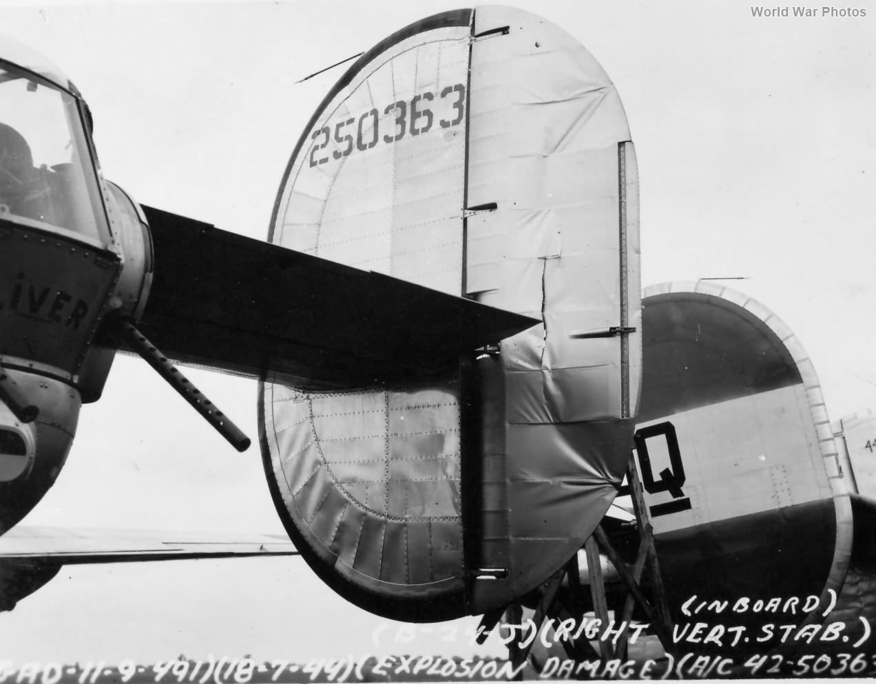
B-24H 42-50363 damaged in the bomb dump explosion at Metfield 15 July 1944. 491st BG, 853rd BS
The horizontal and vertical tail surfaces of the B-24 Liberator were critical components that contributed to the aircraft’s stability, control, and overall aerodynamic performance. Detailed breakdown of their specifications and features:
Horizontal Tail Surfaces:
Airfoil and Area:
- Airfoil Section: NACA section No 0015.
- Total Area: 192 square feet.
- Span: 26 feet.
- Maximum Chord: 7 feet 8 3/16 inches.
Position and Stability:
- Distance from CG: The distance from the design gross weight center of gravity (assumed at 25% MAC) to the one-third maximum chord point was 33.40 feet, approximately 3.5 times the MAC (Mean Aerodynamic Chord).
- Stabilizer Area: Including elevator balance, the stabilizer area was 140.5 square feet.
- Setting: The stabilizer’s normal setting relative to the longitudinal axis was 2.5 degrees.
Elevator:
- Area: 67.1 square feet (51.5 square feet aft of the hinge line).
- Movement: 30 degrees up and 20 degrees down.
- Balance: Aerodynamically balanced with all span-wise elements statically balanced about the hinge line.
- Tabs: Located on the trailing edge, these tabs had an area of 4.95 square feet and were controlled by an irreversible mechanism.
Vertical Tail Surfaces:
Airfoil and Area:
- Airfoil Section: NACA section 0007.
- Fin Area: 123 square feet.
- Rudder Area: 48.8 square feet.
Rudder:
- Balance: Aerodynamically and statically balanced about the hinge line.
- Tabs: Total area of 3.1 square feet, equipped with irreversible controls.
- Movement: 10 degrees right and left of center.
Construction and Features:
Materials and Structure:
- Control Surfaces: Made of aluminum torque box and rib construction, covered with fabric.
- Stabilizer: Constructed as a separate assembly with a smooth sheet metal skin, attached to the fuselage with only four fittings for easy replacement.
Positioning:
- The entire tail assembly was mounted just forward of the tail gunner’s compartment, ensuring the trailing edge did not obstruct the gunner’s vision.