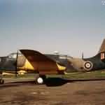
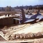
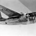
RDB-7B #222 AL384, 1943
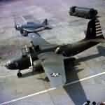
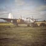
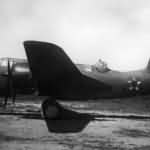
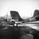
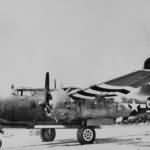
A-20C 42-33381
A-20C 42-33381

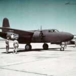
Douglas A-20C
A-20C 42-33381
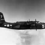
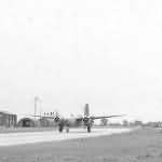
A-20G 42-53775 and BT-13
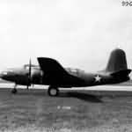
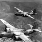
Havocs during Carolina War Games in 1941
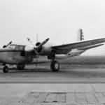
Early A-20A
DB-7 U101

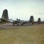
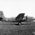
Bostons III
Bostons Mk III 88 Sqn Z2230, AL690 and AL693
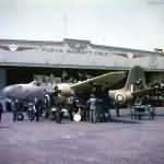
Boston III W8283 at Floyd Bennett Field

Boston III W8268

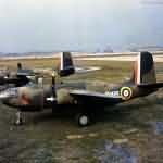
Boston II AH435 1941
Boston II AH435 at at Floyd Bennett Field

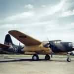
Boston I BB902
Boston I BB902
Boston I BB902

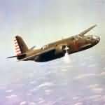
A-20C 1941
A-20A 39-728 3rd BG and P-43

A-20A 39-728 3rd BG
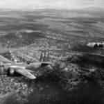
A-20A 27th BG in flight

A-20A 27th BG
A-20A 3rd BG
A-20 War Games 1941
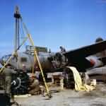
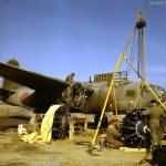
Engine change during the Carolina war games

A-20 War Games 1941

A-20 AL683 24 Sqn, May 1943
A-20 War Games 1941
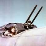
A-20 rear gunner

A-20 S AL 672 8th Air Force Headquarters

A-20 S 24 Sqn, Western Desert

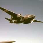
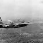
A-20 in flight 1942
A-20 Bassingbourn 1944

A-20 1941

A-20 War Games 1941
Early A-20 in flight
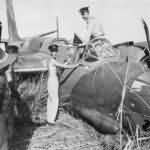
Pilot Rowell after crash landing Boston III A28-8 code DU-J of 22 squadron RAAF, New Guinea 1943
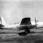
Douglas model 7B, 1938

Douglas production line at the Santa Monica Airport

A-20C #254

A-20 bombs German positions at Cisterna 1944

A-20G-25 Havoc 43-9196 at New Orleans Air Station

Experimental tracked landing gear
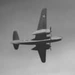
Douglas A-20A in flight

Jet Assisted Take Off of A-20B Havoc 41-2990 at Wright Field

Early A-20 take off

A-20G Havoc “Bevo” shot down at Kokas

Soviet mechanics with Lend-Lease A-20B Havoc 41-3506 at Abadan Airfield in Iran 1943

DB-7 of the French AF
Russian Douglas A-20B 41-2834
A-20G 42-86657 57 in flight

416th Bomb Group, 668th BS, A-20 43-9380 “Denver Darling” nose art, England

Boston III AL754 of No. 107 Squadron RAF December 1942
A-20B 41-2672 at Wright Field

A-20B Havoc Miss Carriage 41-3268 of the 47th Bomb Group in North Africa 1943
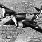
Boston III over Los Angeles, 1941

A-20A over Oahu 29 May 1941

Havoc Mk II AH525
Havoc I BJ496 used for experimental night camouflage trials in February 1941: Extra Dark Sea Grey and a special mix Olive Grey

DB-7B AL904 captured on Java and tested by Japanese Navy
A-20G 42-86573 with 374 gal (1415 liters) external fuel tank
Formation of Douglas A-20A bombers over Los Angeles 1941

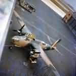
5th AF A-20 Havocs on production line in New Guinea Jungle 1944
Bostons Mk III Z2303 and Z2284 of No 114 Squadron RAF
Havoc with external fuel tank

A-20 of the 89th BS, 3rd Bomb Group during a low level attack on the Lae airfield. G4M1 from 705th Kokutai on the ground

Havoc II AH433 over Mines Field 1941
First DB-7 for Armée de l’Air with narrow vertical tail
Douglas 7B in 1938

A-20A in flight

Early A-20 in flight October 1942
Douglas A-20J 43-21745 “Irene” 8U-S of the 646th BS

Boston bombers in flight over North African Coast 1941

A-20B 41-3040 370 in flight

DB-7 French Air Force 1939

Bostons Mk III RH-D and RH-G of RAF No 88 Squdron searching for Scharnhorst 1942

British Boston III serial W8255, El Segundo Plant
Boston Mk IV (A-20J) 43-9860 BZ403 May 1944

Early A-20 take off 3

Boston III W8315 at A&AEE with Bristol turret
Douglas A-20J 35 of the 47th Bombardment Group Parachuting Supplies over France

A-20J Havoc 43-9639 #18 47th BG named Princess Ruthie
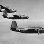
Douglas A-20 Havocs 52 and 51 of the 47th BG in flight

A-20B Havocs #72 41-3665 and #94 41-3144 of 47th Bomb Group

A-20B 14 41-3357 “Dirty Gertie” of the 47th BG over Tunisia, 1943
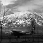
Douglas A-20 94 of the 47th BG Capodichino – Vesuvius before eruption
A-20B Havoc, tail code 14, 41-3357 “Dirty Gertie” of the 47th BG
A-20J #36 43-22070 from 47th Bomb Group in flight

A-20 Havoc #52 “Camille C” of 47th Bomb Group

Douglas A-20B 41-3014. Aircraft carrying variants of the special North West African forces camouflage applied in the field.

Douglas A-20B-DL Havoc #15 41-3356 “Ball of fire” of 47th Bomb Group

A-20 of 47th Bomb Group “Eleven’s Worth” Nose Art

Crashed Douglas A-20 of 47th Bomb Group tail

Douglas A-20B Havocs #88 and #59 41-3132 of 86th BS 47th BG Italy

A-20 from 47th BG and P-47 Thunderbolt crash

Douglas A-20B Havoc 41-3431 #30 of 47th Bomb Group
A-20B Havoc #62 41-3430 “Marty I” of 47th BG and Etna

A-20J Havoc In Action ETO 43-21745 code 8U+S 410th Bomb Group 646th Bomb Squadron

Douglas A-20G world

Douglas A-20G Havoc 43-9432 “Bevo” of the 387th Bomb Squadron hit by flak during an attack on Kokas New Guinea 22 July 1944

Douglas A-20J-10-DO Havoc, Europe Maxine 43-9913

RAF A-20 Boston 1942

Boston III of 24 squadron SAAF

A-20B Havocs of the 47th BG

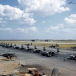
A-20 Orlando Florida 1943
Douglas Boston

destroyed A-20 47th Bomb Group
French Douglas DB-7 North Africa

A-20G Havoc 43-9521 named LITTLE CHIEF of the 90th Bomb Group

French DB 7 bomber

Douglas A-20J-15-DO Havoc Attack Bomber GERRY 43-21747

Douglas A-20J Bomber MISSPLACED Crashed

A-20 Attack Bomber Crashed Into P-47 Fighter Plane on Field

A-20 Attack Bomber JEANETTE

A-20 47th Bomb Group number 70

Douglas A-20 rear view

Boston AL320 over Florida 1943

Douglas A-20J-20-DO Havoc, Aircrew member 43-22068

Douglas A-20 3651

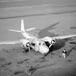
Douglas A-20G crew

Douglas Boston III AL331

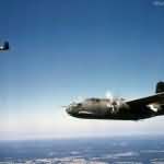
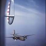
A-20 and B-24 1943 Pacific

Boston Mk III AL492

Boston III Z2302 ex 24 Squadron SAAF

A-20 Havoc LA FRANCE LIBRE, 668th BS, 416th BG 1944

A-20 Havoc Bomber Factory Airfield Long Beach California 1942

A-20G Havoc Old Bleeding Eyes

Havoc of the 47th Bomb Group

French Douglas DB-7 Bomber

A-20J of the 47th Bomb Group

A-20 47th Bomb Group Elevens Worth
Havocs of the 47th Bomb Group 58 and 5

A-20G England 1944
Captured Douglas Boston

A-20G 5H-E of the 668th BS

A-20 Havoc LA FRANCE LIBRE

The cockpit interior of a Douglas A-20 Havoc bomber

Havoc named LITTLE CHIEF of the 90th Bomb Group

Douglas A-20G
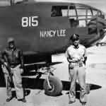
A-20C Bomber Crew Nancy Lee 815
RAF Boston IIIA Bomber 42-33017

A-20C Bomber Crew Nancy Lee 815

A-20 47th Bomb Group
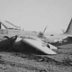
A-20 Wreckage

A-20G Bomber 48

Havoc 47th Bomb Group shark mouth

Havoc 86th Bomb Squadron 47th Bomb Group
B-25G 42-64979 Glamazon PTO

A-20 transparent noses
A-20 Bomber Taxiing for Take Off
A-20 47th Bomb Group 27

A-20 47th Bomb Group 32

Havoc with streamlined 1416 litres external fuel tank

A-20 bomber Orlando AAB Florida 1943
Douglas A-20 Havoc (Boston, DB-7. P-70) was an American attack, medium bomber, intruder and night fighter aircraft of World War II.
USAAC in autumn 1937 published the specification for a new bomber. The design team from company Douglas decided to modify the earlier draft Model 7A through replacement of engines for stronger Pratt & Whitney R-1830 S3C3-G with a capacity of 1100 hp, changing the designation of the project on the Model 7B. Two alternative were proposed to use part of the bow, one transparent to the bombardier and the other covered , equipped with a battery of six machine 7.7 mm guns and two 12.7 mm caliber. For the transparent part of the bow you could mount two gondolas on both sides of the hull, including two machine guns. The other armament were supposed to be machine guns mounted in a 7.7 mm turret or fire through the open bomb bay doors. Capacity bomb was increased to 900 kg. Competitors for Douglas construction were planes North American NA-40, Stearman Model X-100 and Martin 167F. Although the Model 7B was sufficiently fast and agile, he did not arouse interest in the US Army, but he scored for recognition of the French Commission for the purchasing, visiting the United States. The French side participated in testing Douglas machines and eventually ordered 100 machines, increasing the order to 270 at the start of the war. USAAC finally ordered the first copies of the A-20 in mid-1939 years. Another user DB-7 was a British RAF, which because of the situation in France has decided to take the French order for planes (designation Boston Mk I and Mk II, depending on the engine). Later, Brits have already received orders from their own machines (versions Boston Mk III, IV, V). The largest user of the A-20 was the Soviet Union and for their needs were produced more than half of these machines. It was expected to provide 3125 machines of all types in the framework of the Lend-Lease, but ultimately went to the Soviet Union 2901 aircraft. The main route of delivery was overflown by Iran or Alaska because of too much risk to attack convoys by German submarines. These machines are called the Soviet Union the A-20 Boston. Russians often modified the structure of the A-20 to their needs: replaced the rear turret, added torpedoes, changed the structure of the nose and adjusted planes to harsh winter conditions.
A-20 designed as a light bomber has successfully served as gunship aircraft, torpedo and reconnaissance, and even a night fighter. It was easy to use and piloting and easy to build.
Total production: 7478.
General Specifications
- Type: Shoulder-wing cantilever monoplane.
- Wings: The aircraft has a laminar-flow wing section with no center-section; the left and right wing panels attach directly to the fuselage. The structure includes two spars built with unspliced spar caps and integral end fittings. The wings have chordwise stiffeners and flush-riveted metal skin. It features electrically-operated slotted trailing-edge flaps.
Fuselage
- Structure: All-metal semi-monocoque with a practically square cross-section featuring rounded corners.
Tail Unit
- Configuration: Cantilever monoplane type with a dihedral tailplane. It is an all-metal structure with trim-tabs in all control surfaces.
Landing Gear
- Configuration: Retractable tricycle type operated hydraulically. The main wheels retract into the engine nacelles, and the nose wheel rotates 90° to lie flat at the bottom of the fuselage.
Power Plant
- Engines: The aircraft is powered by two Pratt & Whitney R-2800-71 eighteen-cylinder radial air-cooled engines, each producing 2,000 horsepower with two-speed superchargers.
- Propellers: Equipped with three-blade Hamilton-Standard Hydromatic constant-speed quick-feathering airscrews.
- Engine Mountings: These are interchangeable
General Specifications
- Type: Twin-engined attack bomber.
Wings
- Configuration: Mid-wing cantilever monoplane.
- Structure: Each wing consists of an inner section with an integral engine nacelle, an outer section, and a wing-tip. The inner section attaches to the fuselage at five points, and the inner and outer sections are connected at five similar points.
- Design: Single-spar aluminum-alloy structure with stressed Alclad skin.
- Control Surfaces: Framing-edge flaps are located on the inner wing sections, and ailerons are on the outer sections. The ailerons include trimming-tabs, interconnected and controlled from the pilot’s compartment.
Fuselage
- Construction: Aluminum-alloy monocoque with smooth, flush-riveted Alclad skin. The nose and tail cone are detachable.
Tail Unit
- Type: Cantilever monoplane with a 10-degree dihedral tailplane.
- Surfaces: Fixed surfaces are all-metal with stressed-skin covering; movable surfaces have metal frames with fabric covering. Trimming-tabs are installed in both elevators and the rudder, controllable from the pilot’s cockpit.
Landing Gear
- Type: Retractable tricycle type with hydraulic retraction, backed by an emergency hand operation system.
- Mechanism: Main wheels retract backward into the tails of the engine nacelles, and the nose wheel retracts into the fuselage. The system includes oleo-pneumatic shock absorbers and hydraulic brakes.
Power Plant
- Engines: Two Wright R-2600-29 fourteen-cylinder radial air-cooled engines, each producing 1,700 horsepower. They are equipped with two-speed superchargers.
- Propellers: Three-blade Hamilton-Standard Hydromatic constant-speed, full-feathering airscrews, with a diameter of 11 ft. 3 in. (3.43 m).
- Fuel Tanks: The aircraft has four main self-sealing fuel tanks in the wings—two inboard (136 U.S. gallons each) and two outboard (64 U.S. gallons each) of the engine nacelles, totaling 400 U.S. gallons. For long-range missions, it can carry additional auxiliary tanks in the bomb bay and a boat-shaped external tank under the fuselage.
Accommodation
- Crew: Positions include a bomb-aimer (in models with a transparent plastic nose), pilot, and rear gunner. The pilot’s cockpit is located in front of the wing leading-edge, accessed via a side-hinged hatch in the roof. The bomb compartment is positioned aft of the cockpit, followed by the rear gunner’s compartment. Crew positions are armored.
Armament
- Varied Configurations: The aircraft can be configured with different types of noses, including a transparent plastic nose for bomb aiming or a closed attack nose for other versions. Specific armament details are not included in the description provided.
Dimensions
- Span: 61 ft. 3½ in. (17.8 m)
- Length: 48 ft. 4 in. (14.74 m)
- Height: 18 ft. 1½ in. (5.5 m)
- Wing Area: 465 sq. ft. (43.2 sq. m)
Weights and Loadings
- Loaded Weight: 20,000 lbs. (9,080 kg)
- Wing Loading: 43.01 lbs./sq. ft. (209.88 kg/sq. m)
- Power Loading: 7.4 lbs./h.p. (3.36 kg/h.p.)
Performance
- Maximum Speed: 325 m.p.h. (520 km/h) at 14,500 ft. (4,420 m)
- Cruising Speed: 280 m.p.h. (448 km/h) at 14,000 ft. (4,270 m)
- Stalling Speed: 98 m.p.h. (157 km/h)
- Initial Rate of Climb: 2,000 ft./min. (610 m/min)
- Service Ceiling: 25,300 ft. (7,720 m)
between left and right positions. The mountings feature a large metal spinning forward, a stainless steel rear part, and six identical forgings connecting them. The engines have quick-release fittings for lines, pipes, and wiring, and cowling is split into two quickly removable halves. An access door in the firewall allows mechanics to work on the engine accessory section from within the nacelle. Fuel and oil tanks are located in the wings and nacelles, respectively.
Accommodation
- Crew: The aircraft accommodates a crew of three, with all positions armored.
Armament
- Nose Configurations: Various fuselage nose types allow for different armament installations, including a transparent bombardier nose.
- A-26B Armament: Fixed forward-firing armament of six .50 caliber machine guns in the nose, with provisions for up to eight additional .50 caliber “package” guns under the wings, mounted in pairs outside each engine nacelle.
- A-26C Armament: Features a transparent bombardier nose and two fixed .50 caliber guns. Defensive armament includes two twin .50 caliber machine gun turrets, one above and one below the fuselage. These turrets are remotely controlled from a gun-sighting station aft of the wings, with aiming via periscopic sights. The upper turret, when locked in the forward position, can be fired by the pilot along with the nose armament.
- Bomb Bays: Internal bomb bays with hydraulically-operated doors, and external bomb racks under the wings.
Dimensions
- Span: 70 ft. (21.35 m)
- Length: 50 ft. 9 in. (15.47 m)
- Height: 18 ft. 6 in. (5.64 m)
- Wing Area: 540 sq. ft. (50 sq. m)
Bibliography:
- Scott Thompson – Douglas Havoc and Boston: The DB-7/A-20 Series, Crowood Aviation Series 2004
- William N. Hess – A-20 Boston at War
- Roger A. Freeman – Douglas A-20 Havoc U.S.A.A.F., 1940-1945, Camouflage & Markings Number 20
- Jim Mesko – A-20 Havoc in action, Squadron/Signal Publications Aircraft Number 144
- Pilots Manual Douglas A-20 Boston & Havoc, 1940
- Harry Gann – The Douglas A-20 (7A to Boston III), Aircraft Profile Number 202
- Richard J. Caruana – Douglas A-20 Boston / Havoc, Warpaint Series No. 32
- R. Johnson – American Attack Aircraft Since 1926, Mcfarland
- William Wolf -The Douglas A-20 Havoc, The Ultimate Look:From Drawing Board to Peerless Allied Light Bomber
- David Doyle – A-20 Havoc In Action
- United States Army Air Force – Douglas A-20 Havoc Pilot’s Flight Operating Instructions
- Andrew Thomas, Chris Davey -Defiant, Blenheim and Havoc Aces, Osprey Aircraft of the Aces
- Robert A Watkins – Battle Colors, Volume III: Insignia and Tactical Markings of the Ninth Air Force in World War Two
- Dana Bell, Don Greer – Air Force Colors, Volume 2: ETO & MTO 1942-1945 – Squadron Signal Aircraft Specials series 6151
- Dana Bell, Don Greer – Air Force Colors Volume 3: Pacific & Home Front 1942-1947, Squadron Signal 6152
- Robert Watkins – Battle Colors Volume V: Pacific Theater of Operations: Insignia and Aircraft Markings of the U.S. Army Air Forces in World War II